RAYVOSS Transient Voltage Surge Suppression.

Finally a suppressor you donot have to replace!
Tested to be the safest on the market, Strikesorb modules and Rayvoss systems are designed to absorb and dissipate the excess energy of repetitive lightning strikes and power surges without performance deterioration.
Superior performance. Uninterrupted protection. No problems.
Raycap surge protection devices provide safe, uninterrupted protection up to 200kA per module without requiring maintenance even under harsh environmental or poor power quality conditions.
Our RAYVOSS TVSS, equipment withstand 4000 Amps clamping current and above!
In an effort to satisfy the testing requirements of NEMA LS1 for maximum surge current ratings above 200kA per mode, tests are performed on individual modules or on components within the TVSS device. This is not in compliance with the NEMA LS1 definition of the maximum surge current rating. Extremely high ratings cannot be tested on a complete TVSS unit since few independent laboratories have the capability of producing the required 8/20us test waveform beyond 200kA. Some manufacturer publications continue to suggest that devices rated 250kA or above are necessary for adequate protection at service entry. An effective evaluation of TVSS performance requires an investigation of test reports and only reports demonstrating that tests were performed on a complete unit are legitimate.
Actually our RAYVOSS TVSS systems could be installed behind a clamping current of 4000 Amps, class L Time delay fuse at available fault current of 200kA.
We do not have competition at the moment. Our TVSS is the best product in the market by far.
For more informatin and details of Facility and Tower Protection, click on this link:
RAYVOSS Typical communications protection diagram.pdf (57,3 kB)
Rayvoss TVSS surge suppressors are unsurpassed in protecting sensitive electronic equipment from damage causing transient surges that are injected on AC power feeds regardless their source.
Transient threats generated by lightning activity, utility switching operations, power factor correction, and from other electrical loads are eliminate by the Strikesorb Suppression components utilized by the Rayvoss Surge Suppression system.
Rayvoss and Strikesorb SPDs offer the following desirable attributes:
Strikesorb and Rayvoss fully comply to the recent changes of UL1449 2nd edition safety standard, effective February 9, 2007
High current handling capability, Low let-through voltage, Safe and maintenance free operation technology with thousands of installations worldwide. The Strikesorb-40 and Strikesorb-80 modules have successfully passed the 3-cycle testing at available short circuit currents of 65kA rms and 85kA rms respectively. This enables Strikesorb to be integrated within panelboards, switchboards, switchgear, motor control centers, etc, without conducting additional UL testing. The unique, fuseless design of the Strikesorb module allows direct installation on the busbars precluding the need to install additional fuses or interconnection wires.
Strikesorb-40 and Strikesorb-80 modules have also been successfully tested according to UL1449 at available fault current of 200kA with an upstream fuse of 4000A.

Lightning Protection System Grounding
A properly designed and installed lightning protection mitigation system is the best defense against damage.
Though unpredictable, lightning is a very common event around the world. There are more than 40,000 storms every day producing more than eight million lightning strokes. These strokes can result in fires, damage to buildings, and breakdowns to electrical, telephone and computer installations. Damage results from electromagnetic fields from the lightning stroke, voltage differentials in ground systems, and structural damage from ohmic heating or mechanical forces. Damage can be attributed to insufficient direct-strike protection, inappropriate grounding and bonding that permit lightning currents to flow near susceptible electronics, and deficient Transient Voltage Surge Suppression (TVSS) protection.
What can be done to protect personnel and capital investments? The best approach to prevention is a properly designed and installed lightning protection (LP) mitigation system (Reference NFPA 780, UL 96 and UL 96A for LP equipment and proper installation procedures). The foundation upon which the LP system is built is a properly designed grounding electrode system, complemented with proper bonding practices, to create an equipotential plane and the application of TVSS to all power, communication and data signal lines.
The properties of a lightning stroke are indeed impressive, with an instantaneous power of over one Megawatt and, on average, a peak current level of 30,000 Amperes. There are three main lightning interactions that need to be considered:
1. Direct lightning stroke to the facility
2. Near stroke that induces large voltage impulses in metal conductors
3. Ringing results that occur when a tuned cable captures similar frequencies from the radiated stroke.
Lightning Protection
The most popular methods of lightning protection have involved the use of passive Franklin air terminals, horizontal and vertical conductors or combinations thereof. The LP system is dependent on the ground electrode system to effectively dissipate lightning energy into the earth. The characteristics of a ground system under the impulse conditions of a lightning stroke are important if an effective LP ground system is to be implemented. This ensures that the grounding system provides low ground impedance and not just a low resistance. This is a central point to the philosophy of LP ground system design.
The impulse from a lightning stroke is comprised of both high- and low-frequency components. The wave shape of the impulse is characterized by a very steep rise in voltage and current followed by a long tail of excess energy content. The high frequency is associated with the fast rising front while the lower frequency component resides in the long, high-energy tail. Because of this steep rate of current rise, the inductance of the ground system becomes a central point of the design. The voltage rise, known as Ground Potential Rise (GPR), is dependent not just on the system resistance, but more importantly, the impedance (inductive reactance) of the system. The voltage rise can be expressed by the following formula, where I (A) is the instantaneous current, R (Ω) is the system resistance, L (µH) is the inductance of the system, and dI/dt (kA/µsec) is the current rate to peak of the impulse.
The injection point on the structure can reach hundreds of thousands or even millions of volts relative to remote earth, due to the lightning stroke. The dominant factor attributed to this large impressed voltage is the product of the inductance and the rapid rate of current from the impulse. It is this type of large voltage rise that leads to the hazard known as flashover — arcing from the LP system to an adjacent metallic conductor due to the dielectric breakdown of air between the conductors. Therefore, a low impedance ground is essential to the performance of the LP system.
Grounding Systems.
The ultimate goal of a LP ground system is to dissipate the energy from the lightning stroke into the earth, safely and efficiently. The efficacy of the system is one in which the potential rise of the surrounding earth is minimized and the rate of potential fall from the injection point is maximized. Step and touch potentials are maintained to safe levels and an equipotential ground plane is created to ensure the safety of equipment and personnel. Equipotential bonding is used throughout the installation to eliminate damage caused by differential ground potentials. Note that the National Electric Code (NEC) requires that the grounds from all systems including, power, cable, telephone and LP be bonded together.
The LP grounding system must be robust and constructed from materials that will perform for the service life of the building or structure that it is protecting. Inductance and skin effects are the major considerations in selection of conductors, connectors and installation practices. Radials constructed of flat strip or cable, and typically embedded in a ground enhancement material, are the most effective electrodes in reducing GPR and directing lightning energy away from the point of injection. Other commonly used electrodes include ground rods, plates, and enhanced or electrolytic ground rods.
Exothermically welded connections provide the lowest inductance path for high frequency lightning surges while providing the highest level of reliability. They are mandatory for below-grade connections and reduce the concern of corrosive deterioration.
Soil Considerations
Knowing the resistivity of the soil is important since the resistance of a ground electrode or a complete electrode system is directly proportional to soil resistivity. The most common method utilized for measuring soil resistivity is the Four Point Method using the equally spaced Wenner Arrangement. This method is commonly referred to as the Four Pin Method. The Fall of Potential Method is most commonly used to measure the resistance of a ground electrode system, though in some situations, clamp-on style ground testers provide valuable information. The resistance of the installed systems is typically under five ohms.
Knowing the soil resistivity allows the designer to apply what is known about LP grounding conductors and electrodes. For example, if the upper layer is poorly conductive, larger radial wire or strip should be used to reduce the inductance between ground rods, and the spacing between the rods should be decreased. Changing conductor size and rod spacing is required due to the soil not shunting the radial inductance as it would if this layer were conductive. The impedance of the radial conductors can be greatly reduced by the addition of conductive ground enhancement materials around the conductors. Furthermore, high resistivity soils can cause a high concentration in the electric field around an electrode, which may cause arcing in the soil that can fuse the soil into a glass material (fulgurites). This glass material will no longer be conductive.
A periodic inspection program is needed to ensure that continuity exists throughout the ground system. Annual testing is recommended to verify that the system is operating at an optimal level. Regular inspections need to test both the electrical resistance of the system to remote earth as well as continuity within the system.
For more informatin and details of Rayvoss TVSS, click on this link:
https://www.netsolutions.com.gt/
For a Strikesorb Consept animated presentation, click on this link:
Tags:
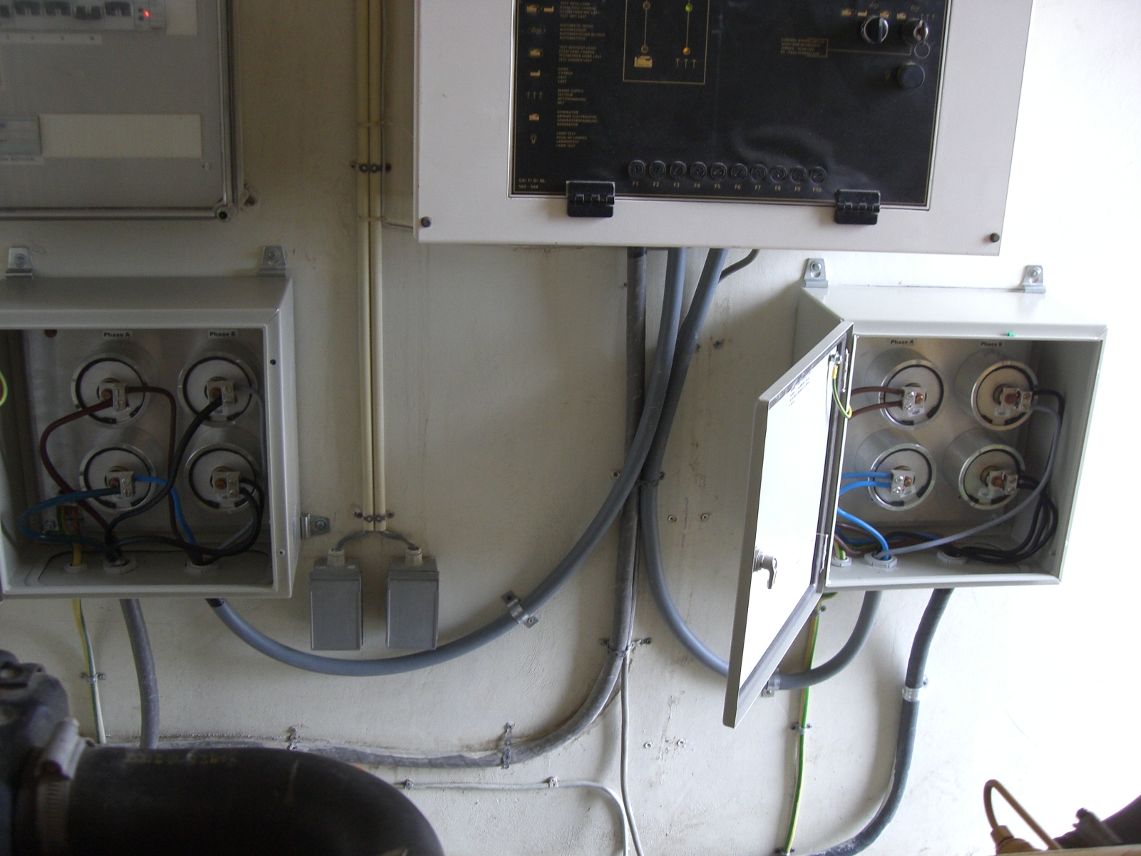
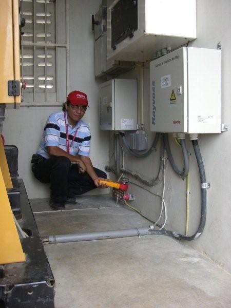
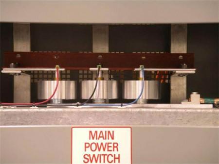
Photo Gallery: RAYVOSS Transient Voltage Surge Suppression.


![]()